Tuesday, August 2, 2011

Tech Tip: Quick Tips for VoluMill Universal

Here are some useful things you might not know about VoluMill Universal:

The Tab Key
 
If you need to cycle through possible selections, use the Tab key. For example, suppose you are hovering your mouse over the model below:


The part turns a salmon color, telling you that if you left-click or right-click your mouse, it will be selected. However, notice the cursor: it's shaped like a "+" sign with a Tab arrow on top of it. That tells you there are multiple possible selections, and you can press the Tab key on your keyboard to cycle through them all. This can be particularly useful when your part and stock surfaces overlap and you want to make sure you select the right one, or if you want to select a toolpath on a part so you can backplot, verify, or post process it.

Translucency

If you are importing stock as well as part surfaces, you may have some trouble seeing the part, since the stock covers the part completely. Simply right-click on the stock and select Toggle Translucency from the menu, and you'll be able to see the part through the stock:


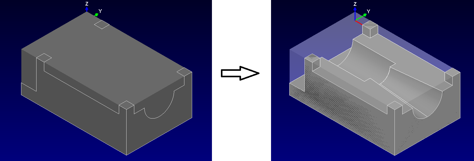
Using the Tab key, you can easily cycle between the part and the stock when you are ready to select them for a VoluMill operation.

The Power of Post Processing

You probably know that you can use the built-in postprocessor to create G-code to run on a milling machine. But did you know that you can also use the post processor to create CL data or other custom formats? VoluMill Universal automatically installs post processors that generate CL data you can use to bring VoluMill toolpaths into Siemens NX, CATIA, Mastercam, and other popular CAM programs. And because Post Processors are fully customizable, you can generate other formats as well; just use the installed posts as your guide.

Deleting Chains

If you make a mistake in chaining or want to remove a chain you've made while creating a 2-axis toolpath or adding boundary containment chains to a 3-axis toolpath, just right-click on the chain and select "Delete":


If you make a mistake, don't worry; that "Back Up 1 Step" button is a general-purpose Undo button, so you can undo the delete with it.

The right-click menu often has useful object-specific functionality on it. For example, right-clicking on a toolpath gives you shortcuts for backplotting, verifying, and post-processing the operation.

View Shortcuts

You can hold down the Alt key and press the numbers 1 through 7 to cycle through common views (1 is the Top view, 7 is an Isometric view). Other useful mouse and keyboard commands include
  • Holding down the left and right mouse buttons at the same time and moving the mouse does a zoom
  • Rolling the mouse wheel does a "smart" zoom around the mouse location
  • Holding down the middle button or mouse wheel and moving the mouse rotates the view
  • Holding down the Alt key and the middle mouse button and moving the mouse pans the view
  • Holding down the Ctrl key while clicking the left mouse lets you select multiple objects at the same time.

"X", "Y", and "Z" in dialog boxes

Most dialog boxes give you an easy way for you to get information from the model into the dialog box. Suppose you're programming a VoluMill 3-Axis toolpath and you need to get the top of the material from the model. Type in the letter "z" and press ENTER:


The dialog minimizes itself and allows you to select an object in the view. You can snap to an endpoint of a curve, a vertex of a mesh, etc., and use the TAB key to cycle through possible snaps. Once you've selected the object, the dialog will pop back up, with the correct z-value of the geometry you just selected inside the "Top of Material" edit box. You can use "x" or "y" to get those coordinates, too.

We hope these tips help you get the most out of VoluMill Universal. Visit http://www.volumill.com for more information, or follow us on Facebook or Twitter so you can get the latest news and tips from us automatically. Just click the links on the right side of this page to follow us.

Sunday, July 17, 2011

Announcing VoluMill v4.0


The latest version of the ultra high-performance toolpath engine includes the Active Chip Thickness Control (ACTC™) interface, which makes it easy to achieve even greater reductions in rough milling cycle time, and the new Non-Concentric Milling technology, designed to reduce tool load and improve chip clearance.

Radial chip thinning has been a common topic of discussion over the past decade or so. It is a real phenomenon, easily defined and illustrated, but the benefits of which have proven elusive. ACTC now makes those benefits attainable by moving beyond the concept of chip thinning and giving customers direct control over the actual chip thickness throughout their rough milling programs. This active management of chip thickness is producing reductions in cycle time up to 35% over current VoluMill toolpaths – which were already up to 5X faster than typical toolpaths.


VoluMill 4.0 has been reengineered from the ground-up to improve machining dynamics during arc moves. Toolpaths have always contained arc moves that share the same center point and entry angle as arc moves on previous passes. Unfortunately, when the tool enters these arc moves, the tool load increases quite suddenly. Our new Non-Concentric Milling technology locates arcs at different center points, so that each successive pass begins its arc move sooner than on the previous pass. As a result, the tool load changes more gradually, and the chips evacuate more easily.

VoluMill has proven itself time and time again as the fastest way to increase the competitiveness of machining operations. CEOs and CFOs see increases in profitability and greater return on capital assets. Sales people have found they can be much more competitive with bids. Operations Managers enjoy increased shop throughput and scheduling flexibility, plus reductions in cutting tool costs and inventory. NC Programmers benefit from the quick learning curve and ease of use. And machine operators just plain love how it sounds when cutting.

VoluMill runs as an integrated solution inside many industry-leading CAM systems. The standalone VoluMill Universal™ product, designed to work with any CAD/CAM system, is also available.

Tech Tip: Toolpath containment

Most integrated versions of VoluMill currently support toolpath containment: limiting the extent of cut to a user-defined area. In version 4.0, VoluMill Universal includes this powerful feature for the first time. Here's how it works.

First, import a part and create or import a stock like this one:


Next, create a VoluMill 3-axis operation. After entering your tool information, along with feeds and speeds, go to the Cut Control tab. Notice the "Containment chains:" item and hit the "Select..." button:


Then chain one more more containment boundaries using the same chaining functionality you'd use to create a VoluMill 2-axis toolpath. You might be able to use curves that you imported along with your part model, or you can use File->Merge to bring in a DXF, IGES, or STEP file containing containment curves. In this example, we'll chain a sequence of curves below the walls of a pocket:


Exit the chaining dialog and click OK. Only the pocket inside the containment boundary is machined:


You can do all sorts of things with toolpath containment; you can have as many boundaries as you like, and using the chaining dialog, you can designate containment boundaries as either Part or Material. Part boundaries are "tool-to" boundaries, like the one above; the tool edge can come up to the boundary but not cross it. Material boundaries act to limit the stock: the tool can pass through the side of a Material containment boundary, but it won't do any cutting outside.

Regardless of the type of containment you use, though, the tool will never violate a part or check surface. So if you import a full solid model and select it as part surfaces, toolpath containment lets you program some areas of the model without worrying about the tool colliding with the model elsewhere.

VoluMill integrated clients are designed to work seamlessly with the host CAM systems, so the toolpath containment interfaces in those clients do differ somewhat. Consult the documentation for those systems, or drop us a line at http://www.volumill.com/ if you have any questions.

Wednesday, July 13, 2011

Machining Tip: How do I get started?

You probably know that VoluMill is designed to be run at feeds and speeds much faster than traditional toolpaths. But if you're just starting out, how can you select the best parameters for your machine?

In a series of tests, we've come up with some rules of thumb to help get you started. Of course, after dialing in these parameters, you can use your own instincts and experience to fine-tune things.

The four most important parameters to set when programming a VoluMill toolpath (or, really, any toolpath) are the spindle speed, feedrate, radial depth of cut (or stepover), and axial depth of cut. The spindle speed and feedrate are computed from two fundamental parameters: the surface speed and the chip load. We recommend the following rules to get started:
  1. Maintain the chip load recommended by your cutting tool manufacturer for your material.
  2. Double or triple the surface speed recommended by your cutting tool manufacturer. If you have a good tool and a good holder, you can probably triple it.
  3. Use a stepover between 6% and 40%, depending on the material (see below).
  4. Cut axially as deep as your part and the flute length of the tool will allow.
Of course, you can determine your spindle speed rpm and feedrate based on the chip load and surface speed with these well-known calculations or their metric equivalents:
  1. rpm = (3.82  x  surface feet per minute) / (tool diameter in inches)
  2. feedrate, inches per minute = chip load x rpm x number of flutes
 Determining a good stepover depends on the material and how easy it is to machine. You might use 40% stepover in aluminum, 6% in inconel, and 7% in 6Al4V Titanium. For different types of steel, good numbers seem to be somewhere in between; for example, you could cut 4140 steel at 15%-20%  of tool diameter, softer steels like 1018 at 30%, and 17-4ph stainless at 9%.

  These are only starting parameters, and you may find that you can easily dial the parameters up after your first try. If you feel like you want to get still more performance, try increasing the chip load, particularly if you are using a small stepover. If you are cutting less deep axially, you may be able to increase your stepover as well.